 Fraunhofer Institute for Mechanics of Materials IWM
Laser powder bed fusion: Metals
Introduction
Powder bed fusion of metal with laser beam (PBF-LB/M), a subgroup of additive manufacturing (AM) techniques, uses a laser energy source to locally fuse matter into a part. AM techniques, such as PBF-LB/M, are emerging processes in many industries where they compete with already established bulk manufacturing methods. The decision whether to replace established methods with new AM methods is non-trivial. For wise economical decisions, a detailed comparison between established bulk manufacturing methods and potential AM methods is required. Examples for such comparisons might include manufacturing time, production cost, amount of waste material, process reliability, CO2 footprint and part properties. The required data can be partly gathered by experiments, but also significantly complemented by detailed numerical simulations.
The task
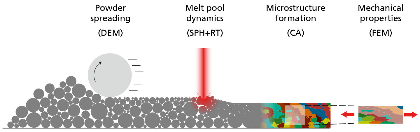
Sequence of simulation steps to cover the full PBF-LB/M process.
We present a simulation chain of a full PBF-LB/M process starting from the powder layer deposition to laser melting and microstructure formation to determining mechanical properties of the manufactured part. The complexity of the process requires a combination of methods each of which we identified as best choice for the respective step. Therefore, the focus of our work is not on improving existing methods but rather on how to couple the methods and to establish an automated workflow. The resulting workflow allows to easily vary process parameters and raw material properties and study their influence on the resulting part properties. The complete process chain is depicted in the adjacent figure and consists of four steps each of which is further explained in the next section.
Results
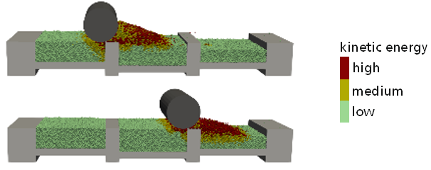
DEM simulation of depositing a new powder layer by using a roller to spread powder from a reservoir into the building chamber.
In the first step, the powder is spread in the building chamber in order to apply an ideally homogeneous new layer. A suitable simulation method must be able to represent the particle size distribution, accurately capture the particle flow behavior and consider interactions with machine parts such as the spreading roller or squeegee. One suitable simulation method is the Discrete Element Method (DEM)], a Lagrangian particle method in which particles interact by repulsion, sliding and rolling friction, viscous damping and cohesion. The application with respect to a PBF-LB/M process is shown in the adjacent figure where a counter rotating roller distributes the powder in the building chamber. The color scheme in the figure indicates regions of varying degree of powder motion. Particles close to the rotating roller have a medium to high kinetic energy due to the interaction forces between roller and powder. With increasing distance from the roller, the influence on the powder motion decreases to the point where powder particles are kinematically at rest. The result of this simulation step is a bed of powder particles as it would occur in the real process. The obtained powder bed’s bulk density distribution can vary depending on powder properties, such as friction and cohesion, as well as on process parameters such as the roller’s translational and angular velocity. The resulting spatial particle configuration in the building chamber can be extracted as initial configuration for subsequent melt pool simulations.
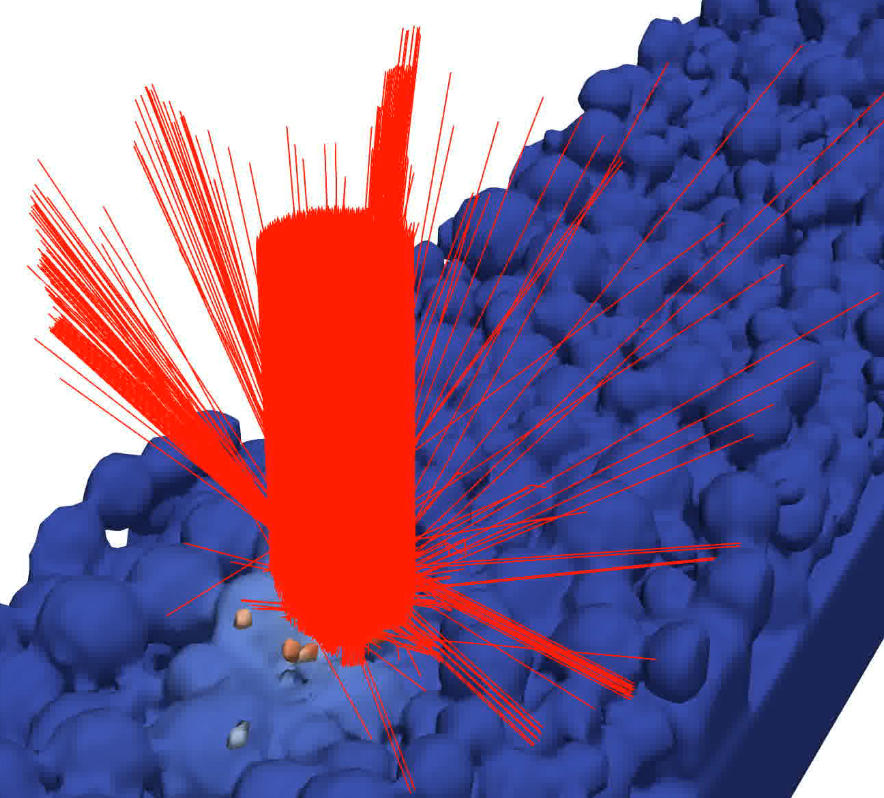
SPH melt pool simulation showing laser beam reflections.
During the PBF-LB/M process, a laser beam source melts locally the powder particles and a melt pool is formed. Upon temperature decrease, the melt pool solidifies again and forms the final part. The melt pool dynamics depend on various, often temperature dependent, physical properties, such as laser absorption and reflection, surface tension, viscosity, heat capacity, thermal conductivity, and gas phase recoil pressure. A suitable method to model comprehensively the physics in melt pools is the Smoothed Particle Hydrodynamics (SPH) method. SPH is a Lagrangian particle method that solves the Navier Stokes, thermal energy balance and mass balance equations. The material property data required as input for SPH simulations is obtained by measurements or by thermodynamic calculations. A laser beam source traverses the powder sample as shown in the adjacent figure. The laser beam intensity is modelled by a user-defined intensity distribution which is spatially discretized by single laser rays with an intensity according to their position. The propagation of the laser rays is governed by a Ray Tracing (RT) algorithm which allows to model reflection and refraction of a ray when in contact with a material surface. The SPH simulation provides information on temporal and spatial temperature profiles, residual porosity, lack of fusion and surface roughness. The SPH simulations could be used to optimize laser parameters and to tailor the melt pool shape for a given material. In this work, we even go one step further and use the obtained temperature profiles as input for another simulation that is able to predict the metallic microstructure.
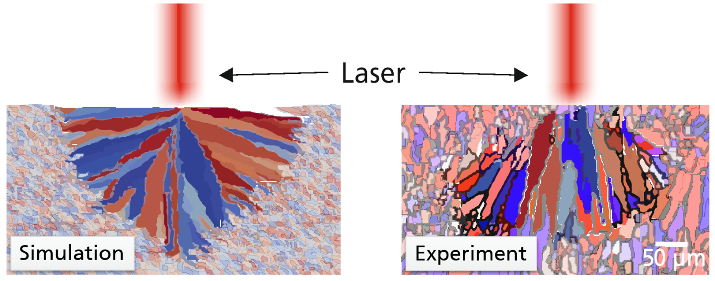
Columnar grain structure in a melt pool in a 2D simulation (left) and in the experiment (right; adopted from Takata, Mat. Sci. Eng. A, 2017).
The temperature history of the PBF-LB/M process leads to complex microstructure formation. Microstructure refers here to the size, shape and orientation of dendritic grains that have formed once the material in the melt pool has re-solidified. The solidification process is governed by a competition between grain nucleation and grain growth. One method to predict microstructure formation is the cellular automaton (CA) which considers local melt pool information, such as state of matter and temperature, to predict grain growth. The growth of individual grains in the solidifying melt pool is described by a dendritic tip velocity. This velocity is proportional to the square of the local undercooling temperature, i.e., the difference of the material’s liquidus temperature and the local temperature. The CA can accurately reproduce experimentally observed characteristics of the PBF-LB/M induced microstructure. For the cross-section through a single laser melt track, the adjacent shows agreement in the microstructure between simulation (left) and experiment (right) where a columnar texture with orientation towards the melt pool center is formed.
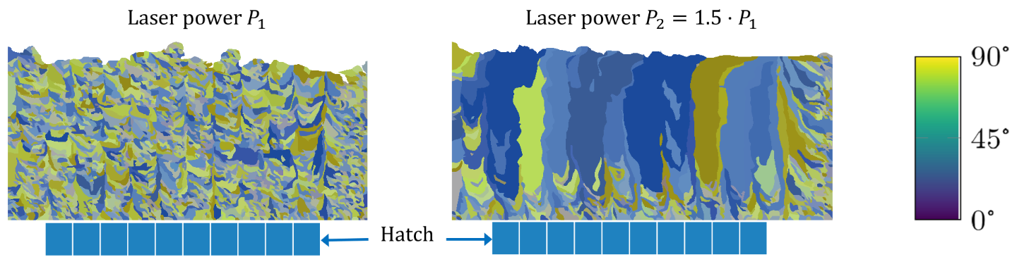
PBF-LB/M grain structures for varied laser power where the color-coding indicates the grain orientation angle as predicted by the CA method.
In a PBF-LB/M process, a laser irradiates for each deposited powder layer several parallel tracks separated by a hatch distance. For the the casae of laser tracks located exactly above each other in subsequent layers, the resulting microstructure in a cross-section through the laser paths is exemplarily shown in the adjacent figure for two different laser powers, which differ by a factor of 1.5. The figure shows that in the case of the lower power many smaller sickle-shaped grains are formed while in the case of the larger power the increased energy density causes a pronounced growth of columnar grains in upward building direction. The resulting grain morphology, i.e. size, shape, and the grain orientation distribution, is used as input for Finite Element Method (FEM) simulations to calculate the microstructure dependent mechanical properties.
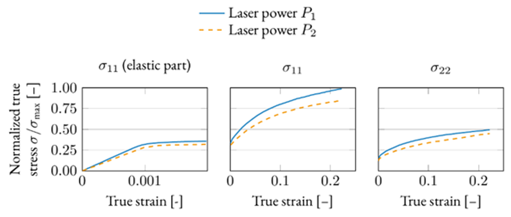
Normalized stress-strain curves, obtained by crystal plasticity FEM simulations, showing the influence of the microstructure caused by different laser powers.
The PBF-LB/M process produces a quite complex microstructure, as shown in the previous section. Thus, accurate crystal plasticity models for polycrystalline metal materials are applied and solved using FEM. This type of models considers the crystallographic orientation of each grain and can be used to describe texture dependent mechanical properties. Based on a numerical homogenization procedure, macroscopic mechanical properties can be estimated once the microstructure model is calibrated. In FEM simulations, representative volume elements of the microstructure can be variously deformed reflecting multi-axial measurements. These simulations provide information on Young’s modulus, yield stress and strain hardening depending on the loading direction. Corresponding stress-strain curves for different stress components of a multi-axial loading case are shown in the adjacent figure. Obviously, the microstructure produced by the smaller laser power leads to a higher homogenized strength and Young’s modulus than the part produced by the larger laser power.