 Fraunhofer Institute for Mechanics of Materials IWM
Co-simulation
Coupling SimPARTIX® with Abaqus/Explicit.
Options
The possibility of coupling discrete element method (DEM) and finite element analysis (FEA) simulations is particularly attractive in order to model contact between granular matter and soft bodies. Co-simulations using smoothed particle hydrodynamics (SPH) and FEA are useful to model fluid-structure interaction (FSI) phenomena including large deformations.
Co-simulation in the cases presented here means the controlled exchange of quantities on the coupled walls between two different simulation codes at each time step. In this surface coupling method these walls are the domain boundaries of each numerical model. The coupled walls on the structural side are in fact all parts, which may get in contact with the particles during the simulation at any time.
At the coupled walls, elastic and kinetic energy as well as momentum are exchanged between the structure and the particles. The particles, hitting the wall, cause reaction forces at the wall, e.g., due to repulsion, cohesion and damping as well as tangential friction. These forces are the structural load applied to the FEA model. The FEA results are new nodal displacements and nodal velocities, which on their part are the input to the particle code describing the motion of the coupled wall. Displacements and velocity are therefore sent back from the FEA code to the particle code.
The implementation of such a co-simulation scheme has been realized using SimPARTIX®, the FEA software Abaqus/Explicit and a communication interface developed at the Fraunhofer SCAI.
Elastic panel
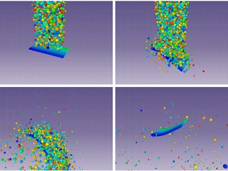
Simulation snapshots of a bulk of particles falling on an elastic panel which is clamped on one edge.
A DEM-FEA co-simulation which shows generic effects of the coupling scheme is presented here. A bulk of particles with different radii is placed above a panel. The panel is clamped on one edge. The freely moving particles are subject to gravitational acceleration pointing downwards. The panel is not directly affected by gravity. A visualization of the simulation is shown in the figure below. The freely moving particles are colored randomly. The panel is colored according to the horizontal position from front to back. The time series shows how the panel first bends due to the particle impacts and swings back later because of stored elastic energy.
Shot peening
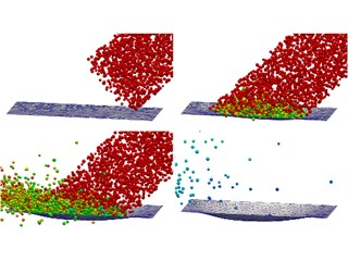
Simulation snapshots of shot peening particles which deform a sheet plastically.
The process of shot peening is resembled in this example. A jet of DEM particles hits a sheet with an impact angle of 45 degrees. The sheet is modelled as a 2D membrane using an elastic, perfect plastic material formulation. The figure displays the course of the plastic deformation of the sheet caused by the particle impacts. The particles are colored according to their velocity ranging from red (high velocity) to blue (low velocity). The deceleration of the particles after contact with the sheet can be observed as well as the shape evolution of the sheet.
Flexible lamella
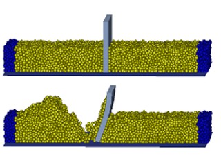
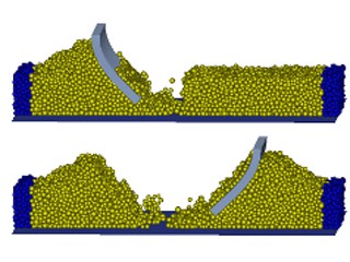
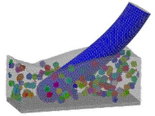
Simulation snapshots of a flexible lamella sweeping cohesive granular material.
A box which is divided into two compartments by a lamella is filled with a random packing of cohesive DEM particles. The lamella is modelled in Abaqus as a hyperelastic 3D solid with Poisson’s ratio of 0.32. The figure shows the back and forth motion of the lamella through the granular material. The top surface of the lamella is path-controlled. The dark DEM particles on both sides are spatially fixed. First, a heap of particles forms on the left side of the box. Then, a similar heap is created by the lamella on the right side of the box. Note also the cohesive particles adhering to the lamella.
Tire traction
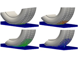
Simulation snapshots of a tire with fixed axis rotating on a cohesive granular bed.
A possible application for the developed co-simulation scheme is the traction of a tire on a granular ground. The DEM force laws can be parameterized in order to represent various types of grounds ranging from sand over mud to snow. In the present case a strong cohesion is used to make the particles very sticky. A constant torque is applied on the tire which is initially at rest. The figure below shows a series of simulation snapshots. Roughly 300,000 particles are simulated. The particles are color coded according to their velocity magnitude ranging from blue (zero velocity) to red (highest velocity). First, the tire accelerates. But then, the tire comes to rest again. The sticky granular material is compacted by the tire motion which causes a torque slowing down the rotation. Some granular material remains in the groves of the tire profile. Note that the tire is modeled as a rigid body in the present simulation. Studies using a viscoelastic tire model are planned for future work.
Bulging and buckling
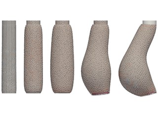
Simulation snapshots of a hose which bulges and buckles under pressure.
The figure shows a time series of a fluid in a hose of rubber-like material. A piston moves downward from the top thereby pushing the fluid into the hose which is sealed by a disc at the lower end. The hose bulges due to the increasing pressure until, finally, buckling into a state of lower energy occurs. The direction of the buckling is purely statistical. The example is obtained from a co-simulation using SPH for the fluid and a hyperelastic finite element model for the hose.
Flow through a hose
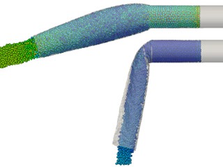
Simulation snapshots of fluids flowing through hoses with different velocities.
The figure shows a fluid in a rigid pipe which is connected to a hose of rubber-like material. A piston moves towards the left through the pipe thereby pushing the fluid out of the hose. Gravity is accelerating the fluid downwards. The faster the piston moves the more the fluid streams towards the left instead of downwards. The piston velocities are 1.8 m/s in the upper case and 0.2 m/s in the lower case, respectively. In the case of the higher piston velocity, the hose bulges due to the pressure. The results are obtained from co-simulations using SPH for the fluid and a finite element model for the hyperelastic hose.
Toothbrush filaments
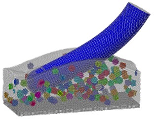
Simulation snapshots of elastic toothbrush filaments with different flexibility.
The figure shows elastic toothbrush filaments which interact with a toothpaste consisting of a fluid and abrasive particles. The filament on the right is three times more stiff than the filament on the left which leads to less bending and, thus, direct contact with the enamel on the ground. The system is periodic in both lateral axes. The results are obtained from co-simulations using SPH with rigid bodies for the toothpaste and a finite element model for the elastic filament.